GNSS system design verification and testing with LabSat
When testing a product which contains an integrated GNSS system, the aim is not usually to test the core GNSS receiver itself (this is often a OEM module that has already been tested), but to verify that the rest of the system responds in the expected way to the information output from the GNSS module.
The traditional method of performing this testing is to have a fixed route to drive, walk or run when testing a system. Unfortunately due to the weak nature of GNSS signals and the constantly moving satellite positions, this method of testing is far from ideal in terms of repeatability. The ability of the LabSat to replay the same scenario multiple times allows for a far greater level of repeatability in testing and so provides far greater confidence that the system is working as expected.
If a problem is found in the field, the highly portable nature of the LabSat 3 also allows for easy recording of the troublesome conditions or scenario. Not only does this allow for verification that the issue has truly been fixed rather than being masked due to different satellite positions, it also allows the problem to be re-produced on the bench; a major aid in debugging any problem.
When testing devices with antenna connectors, the LabSat has a proven track record of being an invaluable aid to product development and testing. Setup is often as simple as connecting the LabSat output to the antenna input port and pressing the play button. Unfortunately, antenna connectors are often large and expensive and so many new portable or wearable devices incorporating GNSS do not include a bulky external antenna connector and can only use their internal antenna.
Testing a GNSS system with an internal antenna
Testing a device with an internal antenna presents a number of challenges; the GNSS engine will get confused if it can see both the LabSat output and real GNSS signals, transmission of radio signals in the GNSS bands are very tightly restricted in most countries, and finally the surrounding environment can have a significant impact on the repeatability of the signals received by the antenna.
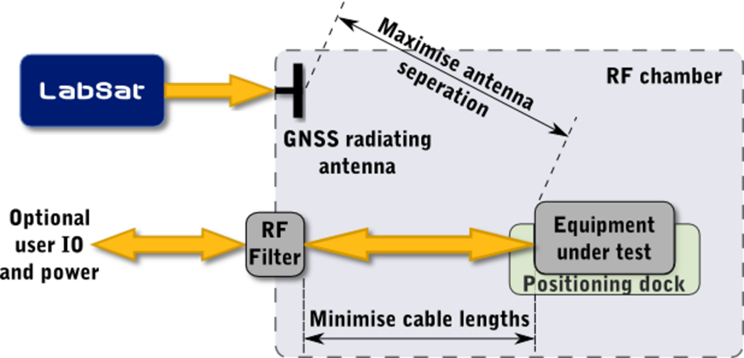
The simplest solution to these problems is to make use of a Radio Frequency (RF) Shielded Chamber by placing the signal output from the LabSat and the device under test together within a sealed metal box, shutting them off from the outside world.
This eliminates two of the difficulties:
- Live GNSS signals are prevented from reaching the system under test.
- The re-radiated signals from the LabSat are confined to the chamber, avoiding the issues with transmissions within the GNSS bands.
The third issue, ensuring a repeatable test, requires two further steps:
- Firstly the chamber should be lined with RF absorbent foam, this significantly reduces the reflections within the chamber and so reduces the potential risks of multipath interference.
- The final step to ensuring a repeatable test is remarkably simple, ensure the unit is always placed in the same location. Ideally this method of locating the device should also lift it off the floor of the chamber in order to move the receiving antenna away from the RF absorbent lining. This could be as simple as a cardboard box with a line indicating unit location or it could involve a dock or mounting bracket fixed to the inside of the test chamber.
Ideally the unit under test should not be placed too close to any of the chamber walls and should be as far as possible from the transmitting antenna. The use of metal within the chamber should be minimised and all cables should be as short as possible. In practice, meeting these recommendations is not always possible. They may compromise the practicality of the test chamber and ultimately have only minimal impact on performance. Due to the nature of RF signals, every product will act slightly differently. When first setting up the chamber, some experimentation may be required to ascertain the best compromise between usability, test repeatability and GNSS performance.


